Core Capabilities
We deliver innovative, precise engineering solutions tailored to meet complex industrial needs with a focus on quality and reliability.

Metering Skids

Filtration Skids

Wellhead Control Panels (WHCPs)

Chemical Injection Skids

Multiport Selector Valve (MSV) Skids
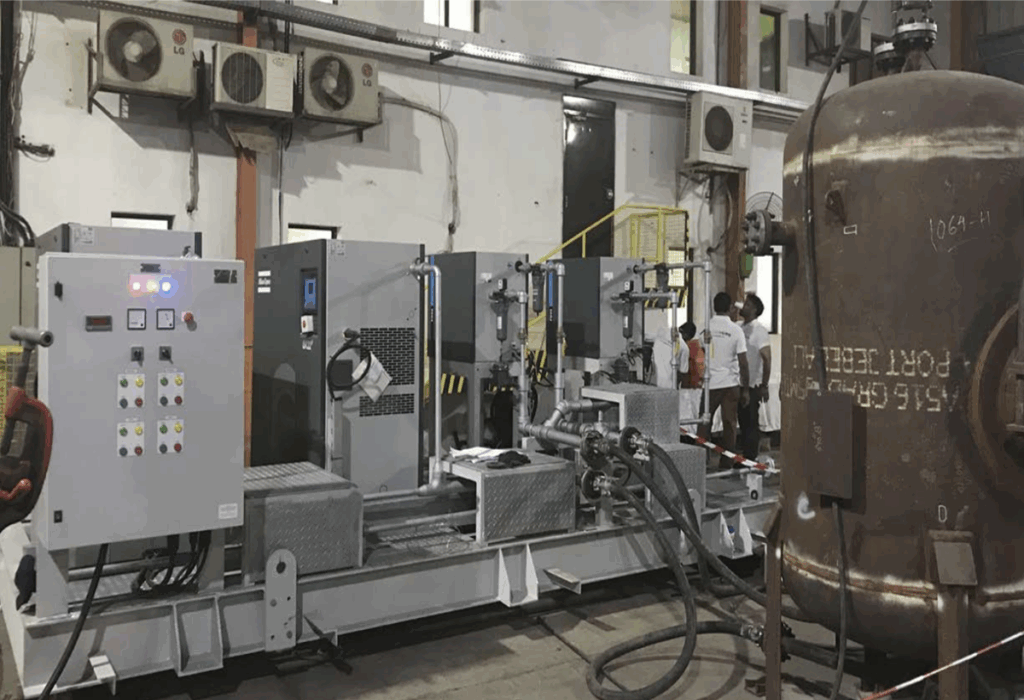
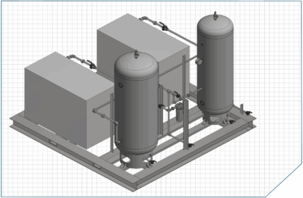
AIR COMPRESSOR PACKAGE
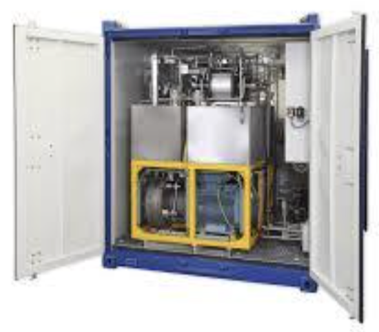
Air Compressor package is an ESG solution – eliminating GHG emissions from pneumatic controlled equipment. Compressed Air Packages can convert fuel gas systems and eliminate methane emissions at well sites and well pads – demonstrating ESG commitments to shareholders, employees, consumers, and regulators.
The main components in the Air Compressor package are the compressor, power source, dehydrator and volume tank. Every air compressor package is designed, engineered and fabricated with a hyper focus on quality.
Features
- Large drop in air oil separator for long life less maintenance cost
- Separate oil sump for the large oil capacity
- All air and oil lines are stainless / coated steel
- Cycling cooling fan
- Microprocessor digital control monitors
- Safety shut down, Phase monitor, Motor amps, Air pressure, Temp, Maintenance log
- Units are built with Highest quality US, and foreign parts
- Warehouses fully stocked with parts
Specification
7.5 HP (5.5 kW)
208 / 230 / 460 V – 3PH or 1PH
27 cfm (125 psi) / 24 cfm (155 psi) / 19 cfm (175 psi)
Air Tanks – Various Sizes and determined by Customer
10 HP (7.5 kW)
208 / 230 / 460 V – 3PH or 1PH
42 cfm (100 psi) / 38 cfm (125-155 psi)
32 cfm (145 psi) / 25 cfm (175 psi)
Air Tanks – Various Sizes and determined by Customer
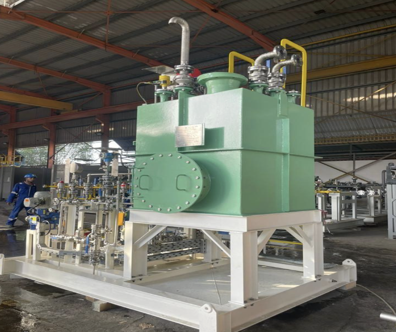
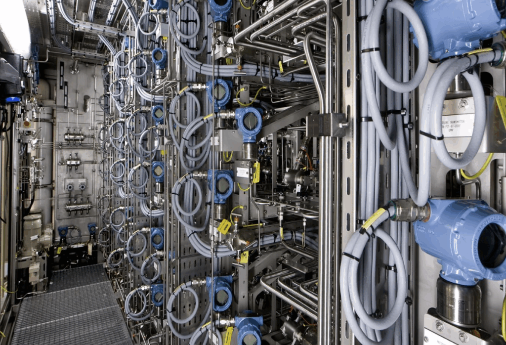
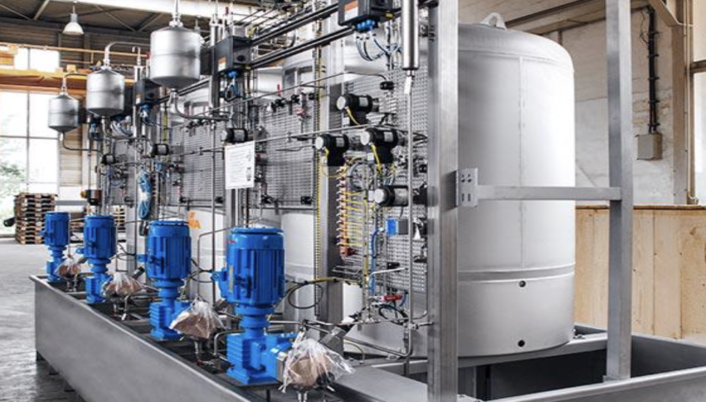
Chemical Injection Packages
Chemical injection packages from Reliance are designed and manufactured to deliver required chemical treatments.
Reliance is a leading manufacturer of chemical injection packages, providing accurate and reliable solutions to meet the demanding needs of the oil and gas industry. We develop chemical injection packages that meet international standards (such as ATEX, API, PED, FRL7800 and ASME) as well as cater client specifications and follow the order of precedence.
Key Features:
- The design complies with international standards, application needs, and client requirements.
- Pump selection based on the operating conditions and the process parameters to be provided by the end user.
- Material selection is done considering the chemical properties and follow the PMS.
- All the items procured as per client provided Approved vendor list (AVL).
- Modelling, STAAD, Piping stress analysis as per client requirement and the available footprint
- We give the validation on the complete packaged engineering.
- 25 years of design cycle and the complete performance guarantee
- Support on SAT and complete servicing plus after sales support to maintain the entire spare parts.
Types of Chemical Injection Package we develop
- We develop 1 working + 1 standby pump package which is the basic requirement from the EPC/End User used for all onshore application.
- We develop Injection Rate Control Device for Multi-Injection mainly used for offshore package’s where space constraints are there.
- We develop Subzero packages used for minus temperatures used mainly for cold climatic conditions.
- We develop very high-pressure pump packages required for downstream injection at times where the design pressure is 12500 Psig.
- We develop containerised package to keep the complete package inside the container to maintain a 25 Degree Celsius for cold climate applications.
- We also do the complete Re-Furnishment of the chemical injection packages where all the usable items are to re-used along with the base frame and the vessel and we will completely change the piping and all the items which are not working in the package.
We developed the chemical injection packages based on the following design parameters:
- Flow Rate (Min./Max.)
- Design Condition
- Discharge Pressure (Min./Max.)
- Temperature (Min./Max.)
- Viscosity (Min./Max.)
- Storage Tank Capacity (Min./Max.)
- Tank Shell Thickness (Min./Max.)
- Available Footprint
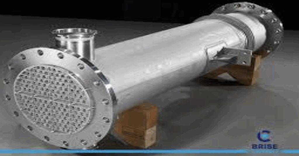
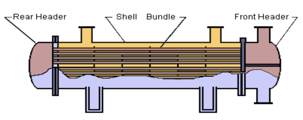
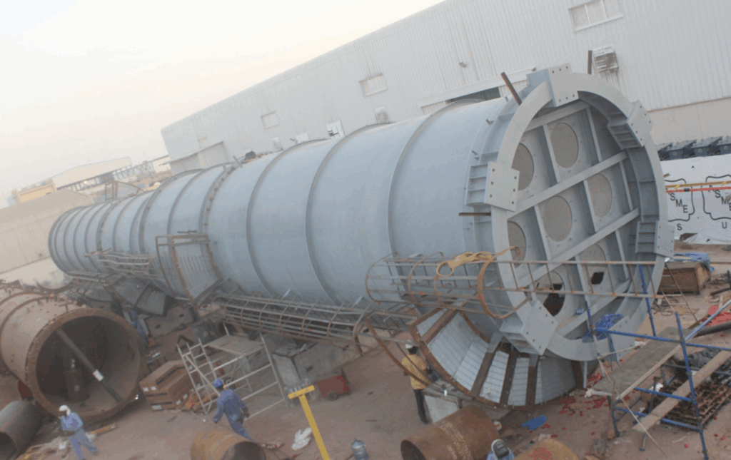
HEAT EXCHANGER
A heat exchanger is a device used to transfer heat between two or more fluids. The fluids can be single or two phase and, depending on the exchanger type, may be separated or in direct contact. Devices involving energy sources such as nuclear fuel pins or fired heaters are not normally regarded as heat exchangers although many of the principles involved in their design are the same.
In order to discuss heat exchangers, it is necessary to provide some form of categorization. There are two approaches that are normally taken. The first considers the flow configuration within the heat exchanger, while the second is based on the classification of equipment type primarily by construction. Both are considered here.
Classification of Heat Exchangers by Flow Configuration
There are four basic flow configurations:
- Counter Flow
- Cocurrent Flow
- Crossflow
- Hybrids such as Cross Counterflow and Multi Pass Flow
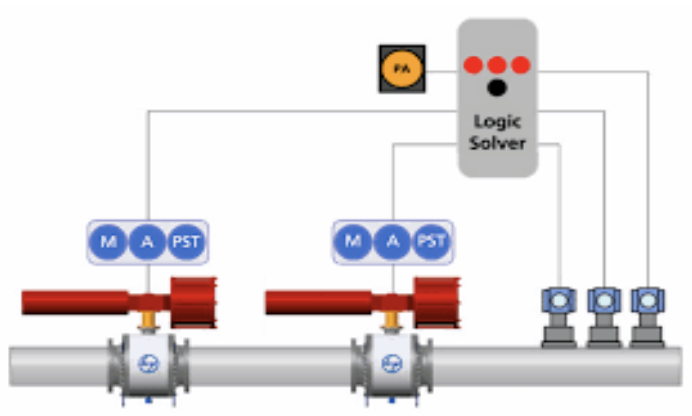
High-Integrity Pressure Protection System
HIPPS is the acronym for High Integrity Pressure Protection System. The main function of HIPPS is an independently instrumented system whose function is to protect an installation from the overpressure produced in the pressure rate of the same, isolating the low-pressure part from it.
- The idea of HIPPS is to be used instead of traditional safety systems such as relief devices with four main advantages:
- Environmental protection: relief systems release the service fluid to the atmosphere, while HIPPS avoid fluid released out the system keeping the environment free of emissions.
- HIPPS must be safety level equal or higher than the traditional relief methods; calculated safety levels show the HIPPS to be ten times more reliable than the traditional methods.
- Creating a frontier between two parts of the installation allows the downstream part of the valves of the HIPPS to have lower pressure and therefore, to reduce the cost of pipes and related pressure equipment’s installed on that part.
HIPPS system is supplied with three Pressure transmitters that monitor the pressure in the line and provide information to the next element.
Reliance Systems also have strong experience and provide Logic solver which is the device in charge of processing the signals received from pressure transmitters and it is configured to send the signal to operate the actuated valves, when the received input is above the pre-configured pressure valve.
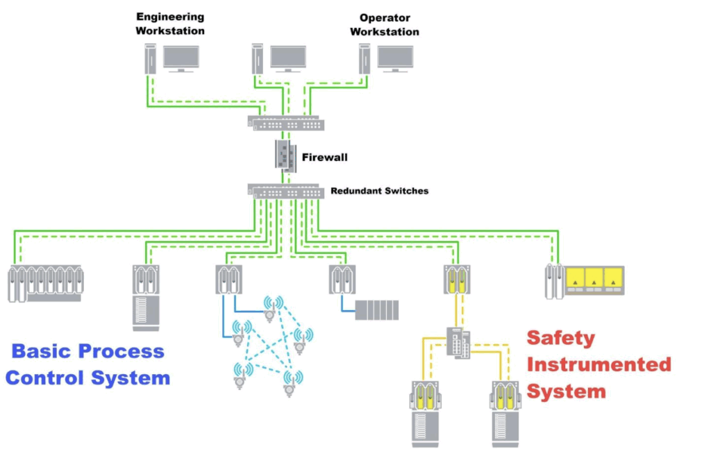
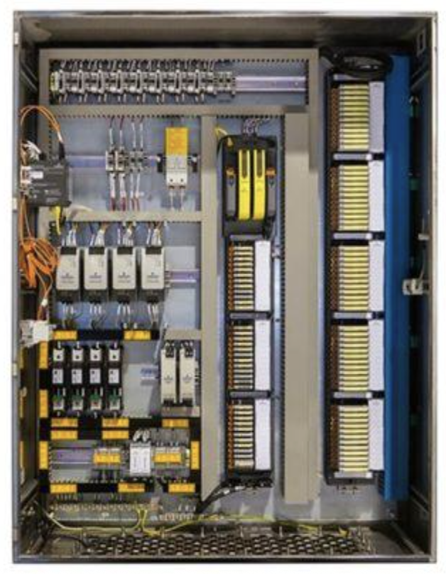
Logic Solver
A safety instrumented system logic solver is typically made up of redundant (double or triple) processors, power supplies, and human interfaces. The safety logic solver will process many safety instrumented functions (SIF) concurrently.
Logic solvers are built with very high-speed microprocessors and perform the required logical functions/calculations within a very short period. Usually, the processing speed lies in milliseconds.
In addition to that, there will be continuous monitoring of the healthiness of the processor (also known as Watchdog), in case of anyone running the processor fails to perform, secondary logic solver takes over the control, and error is reported back to the control room via annunciation system, system alarm, etc.
Usually dedicated Logic solvers – programming device with independent Input / Output modules & wiring is installed across many plants. In a few cases as per the LOPA/PHA study outcome some DCS controllers functions as SIS logic solver.
Safety functions implemented on a certified logic solver must follow the Safety Manual for that logic solver.
Manufacturers of logic solvers from different manufacturers shall meet the requirements of IEC61508 / 61511. Every manufacturer shall register their product with approved Safety system verifying agencies and update their Safety manual.
The number of instrumented LOP (Layer of protection analysis) study outcome credits implemented on a single logic solver in a given LOPA scenario must not exceed the limits of the logic solver.
HIPPS are designed as below,
- IEC 61508: “Functional Safety of Electrical / Electronic / Programmable Electronic Safety Related system”
- IEC 61511: “Functional Safety: safety instrument systems for the process industry sector”
- ANSI/ISA S84.01: “Application of Safety Instrumented system of the Processed Industries”
- Frequency of fail occurrence
- Consideration of the consequences of fail (dangerous failure or safe failure)
SIL level is related to this PFD avg valve and must be considered for the complete functional loop, all its elements and between them, Reliance Systems Process has the capability to make the SIL calculation of the integrated package. Certification to be made by a recognized Third party. Reliance Systems is able to provide complete HIPPS package system qualified for SIL 3 & SIL 4 based on the required redundancies, partial stroke test, etc. In addition, Reliance Systems can provide the complete HIPPS system SKID mounted, with all the components assembled, connected and tested together to be installed directly into the plant.
Safety Integrity Level | Probability of Failure on Demand | Probability of Failure on Demand | ||
SIL 4 | >105 | to | <104 | 100,000 to 10,000 |
SIL 3 | >104 | to | <103 | 10,000 to 1,000 |
SIL 2 | >103 | to | <102 | 1,000 to 100 |
SIL 1 | >102 | to | <101 | 100 to 10 |
Hydraulic Power Unit
The hydraulic (mechanical) HIPPS provides a self-contained, independent protection system operated on demand with one-out-of-two or two-out-of-three pressure sensor inputs, a hydraulic logic solver, and two spring-return hydraulically actuated safety valves. The unit is typically self-powered and can be provided with additional real-time controls via a hydraulic power unit (HPU). This pressurizes the system and opens the safety shutdown valves. The system remains open (armed) until an abnormal condition is detected. If an abnormal condition is detected, then the system closes the two actuated final element valves, protecting the downstream production or facility.
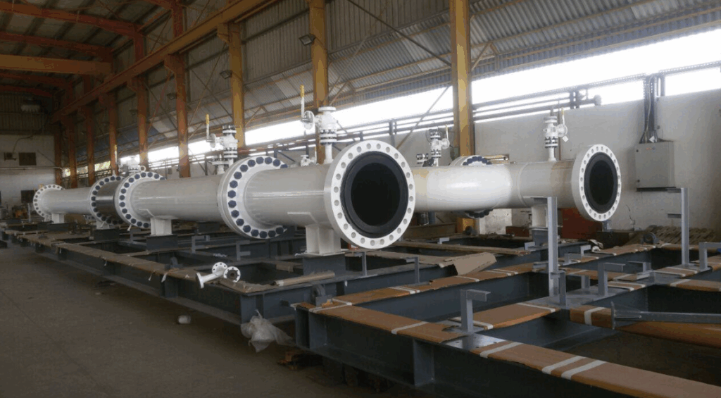
LAUNCHER AND RECEIVER
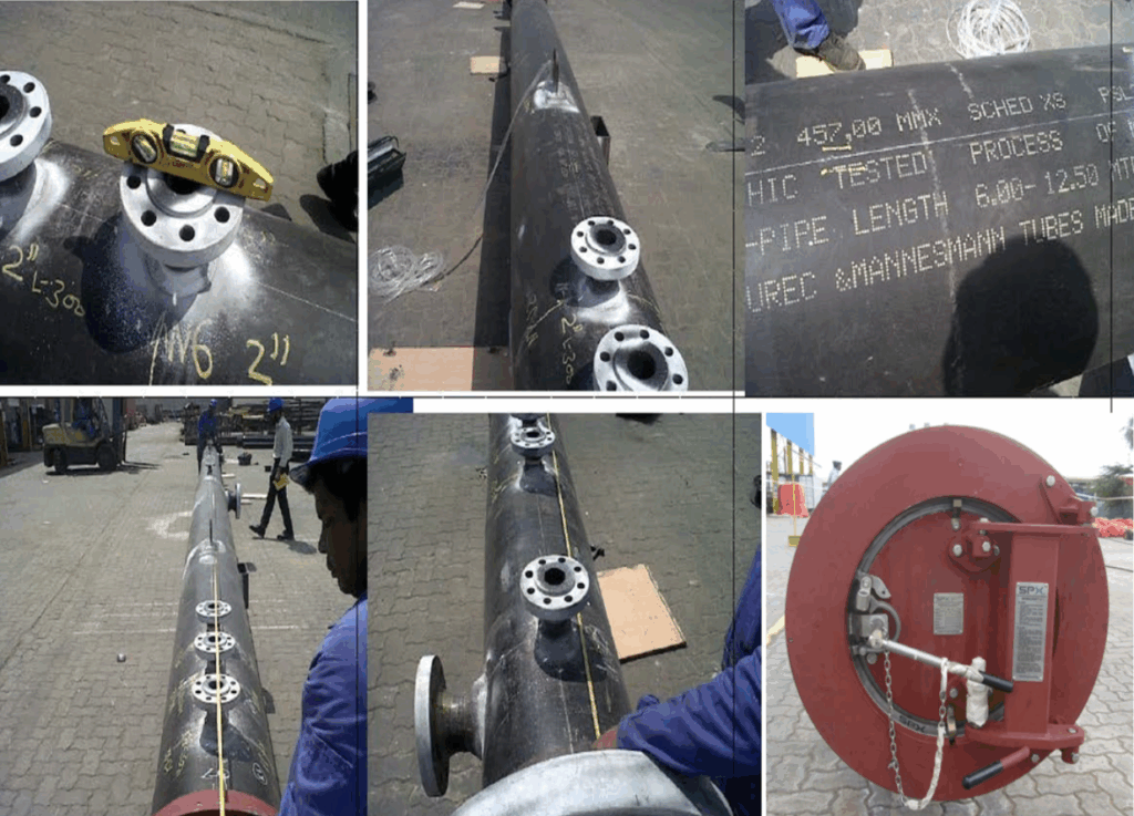
The launchers / receivers, commonly known as pig traps, easily allow the loading or unloading of pigs and spheres into or out of a pipeline. The design of the launchers and receivers engineered by Reliance Energy has developed over the years to ensure intrinsically safe, fast and efficient operation.
There are many names for the launcher / receiver tool, including Pig Trap or Scraper Trap. It is designed for the pigs and spheres to be inserted or retrieved from the pipeline in a safe manner which is efficient so the flow of the medium is not interrupted.
The Launcher / Receiver consists of a quick opening door which leads into a major section which is known as the main barrel which is where the pig / sphere is initially loaded. Following from this is a reducer section which is can be either eccentric or concentric which is used to transport the pig from the oversized section into the minor barrel diameter section, which is the same size as the pipeline and to which the pig is sized, for launching / receiving the pigs without effecting the product flow.
Parameters within the design of the launcher / receiver are important and can be categorised as the basic design parameters, including pressure and temperature of the medium, pipework design etc. and the functional design parameters, including design of the reducer, neck pipe, barrel etc. The experienced engineers at Reliance Energy can design the launcher / receiver to specific requirement in order for the manufacture to be completed in-house to exacting industry standards.
These systems are extensively used in industries such as oil and gas, petrochemicals, power, water, marine, and mining, where pipeline maintenance is crucial for operational efficiency and safety.
METERING SYSTEMS
Flow Metering Solutions
Reliance Systems provides total solution for the custody transfer & fiscal metering packages for oil and gas industries. Our solution in this field includes design, engineering, procurement, construction, installation and commissioning.
Metering Skids
We integrate metering skids with different types of flow meters like Ultrasonic, Turbine, Coriolis, Orifice, PD-meter, with different type of Master Meters and size different types of flow meters for any application and design the best solution based on customers information on process data. Our team of engineers in this field can chose different instrument and equipment [like control valves, motorized valves, strainers, piping materials, pressure and temperature instruments, electrical instruments,] required for the metering skid package.
We do all mechanical design and calculations, P & ld., E & I design as well as Construction, installation, Commissioning and Start-up of a complete metering skid integration.
Flowmeters
Based on the Project’s Process demands and our Engineering Team Experience, we can choose the best Flow Measuring Principle for your Metering Application. This includes Various Types of Turbines, Ultrasonic, Coriolis, Orifice flowmeters, both for Liquid & Gas Metering Stations. The instruments are supplied from Reputable international Vendors.
Control Valves & MOVs
Various types of Control & On-Off Valves [Pneumatic & Electrically Operated] are used in Metering Skids based on the Process requirement. This Includes Ball, Gate, Globe, Butterfly Valves, … which are chosen according to the Projects approved Standards in terms of Size, Material, Operating Conditions, Leakage & Safety Considerations.
Piping & instrument Accessories
Reliance Systems will take care of the supply of Mechanical requirements of the Project including Piping, Flanges, Fittings, Supports, as well as all necessary Bulk material for instrumentation installation.
Design and Procurement of Safety instruments for Metering Skid is also in our scope of work.
Prover Systems
Reliance Systems offers complete stationary proving systems for our Metering Packages, Employing unidirectional, bidirectional and compact Prover technologies. Our Prover systems incorporate industry Leading components to ensure the highest measurement excellence and assuring our customers on improved operational efficiency, reduced operating costs and accurate custody transfer measurement.
Integrated Operation & Management Solution
We offer a dynamic and comprehensive automation, supervision and management system for our proposed metering packages. We develop and supply a modular and upgradeable supervision system customized to your operation & management requirements. Our Engineers can configure any type of flow computers to meet any international standard. We build exclusive control panels for fiscal metering systems and can integrates this any new or existing SCADA / DCS system in the plant.
Some of the key features include:
- Retentive flow totalizers, flow weighted averages…
- Liquid density calculations
- Master meter proving, compact and ball proving
- Batching, batch control, and associated batch reporting
- Instrument validation & diagnostics
- Audit trails at the supervisory level
- Supporting Various Instrument Communication Protocols [HART, Foundation Fieldbus, Single & Dual Pulses, Serial Communication Protocols Modbus RTU.
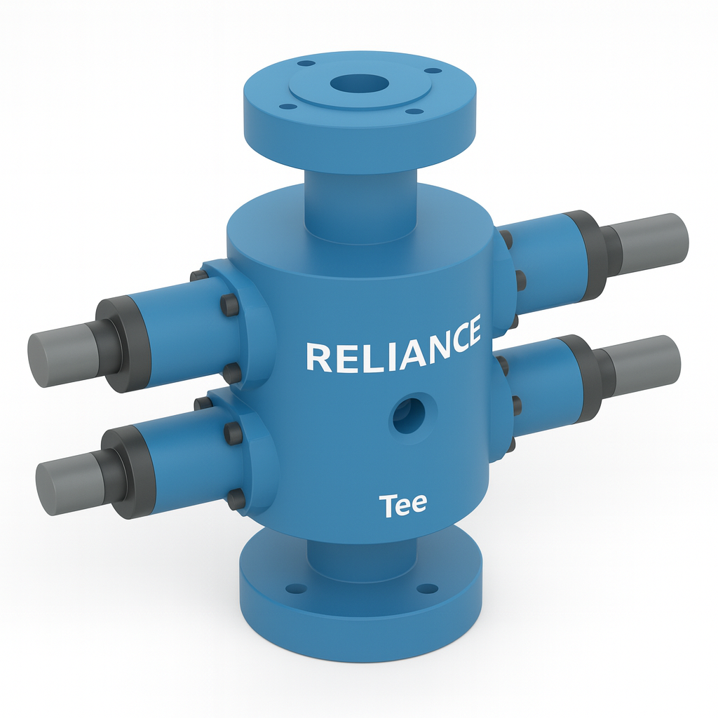
MULTIPORT SELECTOR VALVE PACKAGE
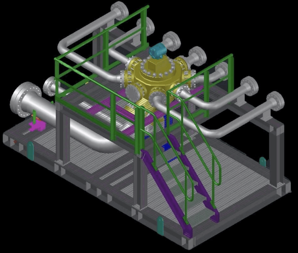
A multiport valve selector skid is a specialized equipment assembly used in industrial processes, particularly in the oil and gas industry. It is designed to facilitate the selection and routing of various fluid streams through different process lines or equipment.
The key component of a multiport valve selector skid is the multiport valve itself, which typically consists of a valve body with multiple inlet and outlet ports. These ports are connected to various process lines, vessels, or other equipment through piping or tubing.
One single MSV can replace an entire arrangement of 2 or 3-way valves for a 3-way well. The selecting system, functioning as a compact manifold, provides an easy and safe way to select the wells you wish to connect to the Multiphase meter or the test Separator. It has eight (8) inlets to connect the production wells, and two (2) outlets: a standard one for production and a selectable one for test purposes. This setup allows one to connect to seven (7) wells, since one of the inlets remains free for field resetting of the seal, and to avoid having a well being connected for test purposes all the time. In this way, using the manual or the intelligent positioning system of the rotor, you can direct each of the wells individually to the testing outlet, while the remaining six continue their production through the group outlet. Multiport Selector Valves are designed to deliver economic test automation accompanied by straightforward simple installation and control.
Key Features
- The compact design of the MSV reduces installation costs and the one basic moving part reduces maintenance. The self-cleaning feature prevents the build-up of scale, paraffin, and other deposits.
- Also the MSV provides fewer sealing surfaces allowing less opportunity for leakage.
- The MSV is offered as either a manual or an automated operation and the automation can be added at any time.
- With 8 inlet ports, the RSV can manifold up to 8 flow lines at one time. It is a compact manifold with reduced size and weight.
- The MSV has a field adjustable seal, with stainless steel scraper for extended service life
- The MSV is especially suited for use with Multiphase Meters.
- Available with two-wire communication for remote control and status indication
- Constructed to applicable parts of API 599.
- Reduces the number of isolation valves in production/test manifolds.
- Operating temperature range:-20° F to +392° F (-29° C to +200° C)
- Available with a multitude of trims and surface treatments for all operating environments.
Oil and Gas Separators
An oil and gas production separator is a pressure vessel that is used for separating the fluid components of an oil and gas well stream into both gaseous and liquid constituents.
The separators can be installed in either an onshore processing facility or on an offshore platform. Separators are also used in numerous applications including gasoline facilities, upstream and downstream of compressors, and liquid traps in gas transmission lines. They can also be found on dehydration unit intakes, gas sweetening units, and various other types of desiccant-filled equipment.
There are more separators on oil and gas locations or process facilities than any other type of process equipment. They are sometimes called scrubbers, slug catchers, FWKO’s, centrifuges, and many other names. However, all of the vessels mentioned above that are designed to separate gas and free liquids have the same fundamental goal.
Separators can be classified in two primary configurations: the position of the vessel and/or the number of fluids to be separated.
Separator Classification
Each of the vessel orientations (horizontal or vertical) can be either 2-phase or 3-phase.
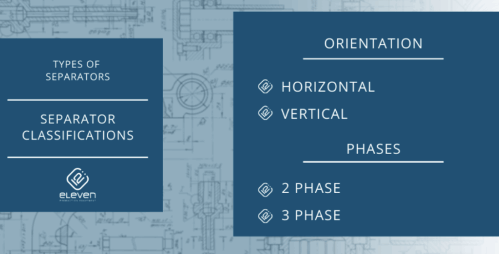
Orientation
There are many types of separators used successfully in the field, but most often, depending on the environment in which they are housed, they can be divided into the following categories:
- Horizontal
- Vertical
- Spherical
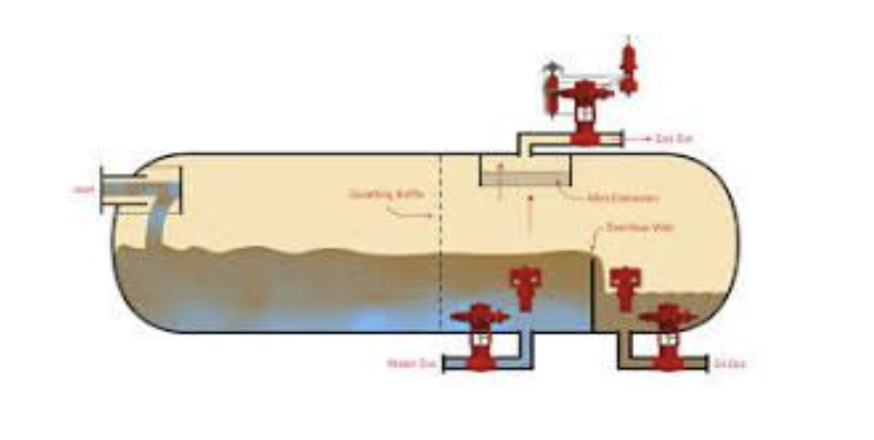
Horizontal Separator
Horizontal separators are versatile vessels that can be used in applications where either gravity or gas pressure is insufficient for effective separating. These vessels are similar in shape and design to vertical contactors, with a collection system, surge drum, and tray packs as described above.
Horizontal separators may be available in diameters between about 3 ft (1 m) and 15 ft (5 m), with heights ranging from 16 ft to 120 ft (5 m to 37 m). For gas/liquid ratios up to about 150 scfm/bbl (0.02m3/mton), horizontal separators work well when equipped with internal tray packs.
In some cases, horizontal separators have been used to handle gas/liquid flow rates as high as 1 MMSCFD/8 MMscf (150 m3/mton). Horizontal separators are available in a wide range of pressure ratings and can be equipped with other features such as trays, weirs, etc., as necessary.
Vertical Separators
Vertical separators can handle a large range of gas and liquid flow rates. Vertical contactors are the most popular type of separators for production service on offshore platforms, but they can also be used in some onshore applications where gravity is not sufficient to separate liquids from the gas stream.
Contactors have a two-phase differential pressure across their bodies, thus allowing more even distribution of liquids on the top and bottom surfaces. Contactors use a collection system that collects free liquids in a surge drum whenever a surge occurs. The level in this drum must be maintained below the level of the trays at all times to prevent re-entrainment of free liquids into a vapor air stream.
Due to the greater vertical distance between the liquid level and the gas outlet, there is less of a propensity for the liquid to revaporize into the gas phase. This type of separator is more difficult and expensive to fabricate and ship in skid-mounted configurations, and it requires a larger diameter separator for a given gas capacity than a horizontal vessel.
However, there are some drawbacks associated with vertical separators that must be considered. The vessel has a large volume and therefore takes up more space than spherical separators; it also requires more piping for connection purposes.
Spherical Separators
Spherical separators offer an inexpensive and compact vessel arrangement. They can handle high vapor and liquid loads with ease. They are particularly suited for the removal of sand and other free liquids (slug load) and medium- and large-diameter gas streams (up to about 12 in [DN 300 mm]).
Spherical separators are low in cost, simple to operate, compact, etc. The trade-off comes in the form of lower efficiency at low gas/liquid ratios. That’s why they are not very common nowadays.
Separator Phase Categories
A typical multiple-effect system consists of a number of individual vessels connected in series, with one or more steam extractions between each vessel. Each stage is generally equipped with an overhead vapor line, a down comer line to allow liquid from the previous stage to enter its separator section, and a steam trunk which supplies heat to the last stage.
There are two types of “phase categories” that separators can be grouped within:
Gas/liquid two-phase separator
Oil/gas/water three-phase separator
Two Phase Separators
Two stage separators, also known as double effect vessels, use two separators connected in series. The first vessel separates the liquid from the vapors coming from the previous vessel, and these liquids are used to strip the second stage. These types of vessels have a separate vapor line at a higher elevation than that of a single-stage unit to provide an area for the purge vapors.
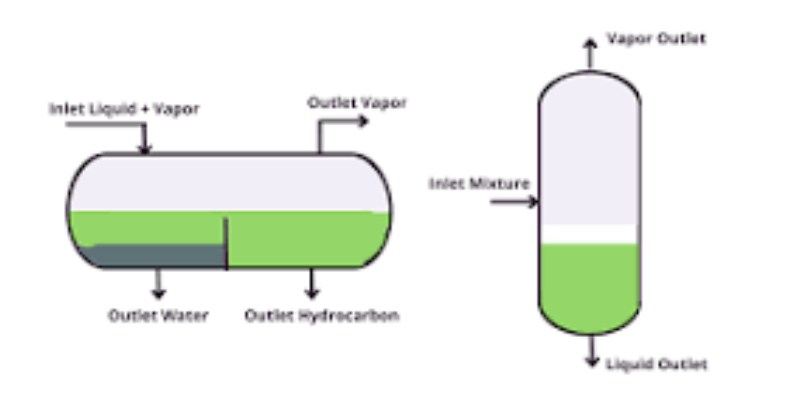
Three Phase Separators
Three-phase separators use a rapid vertical stripping action to recover the gas components from a complex mixture of gases, vapors, liquids, and solids. The three-phase separator consists of two vertically arranged chambers separated by an annular area, in which are mounted radial vanes.
A high velocity stream of steam is passed through the radial vanes for jet entrainment in the chamber below. Stripped crude oil collects in the lower chamber, while gas enters through open slots in the upper chamber. This type of separator is best used in conjunction with a vessel that contains only gas or only liquid, so that the 3-phase separator can fully separate all three fluids.
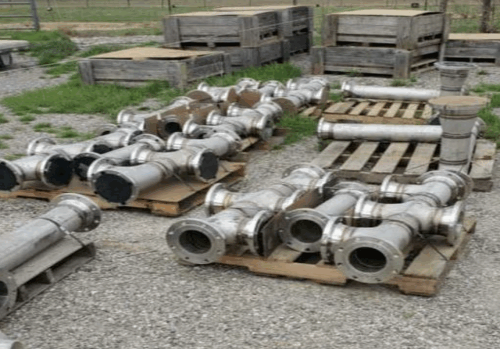
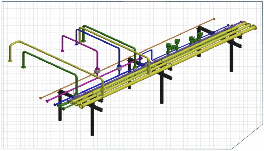
PIPING MODULES AND SPOOLS
At Reliance, we offer turn-key piping modules and spool services – we design, fabricate, and transport the equipment. Our piping modules and spool drawing services include everything from Isometric and assembly drawings to 2D and 3D CAD fabrication drawings for shop floors.
In the last few years, we have emerged as a leading piping spool drawing service provider. Our suite of piping modules and spools been preferred by hundreds of clients to design and install piping for shop floor and large facilities
How does Reliance Energy Assist?
- Piping spools are designed, fabricated, and transported over great distances without pipes shifting or moving
- Each part is fabricated individually and then fully assembled at a shop; then broken down and shipped
- Each spool is categorized with its own set of drawings and information; bolt packages developed and piping bolts A-A, B-b, C-C, and so on
- From small piece jobs to full locations, save money and time by allowing our team in manufacturing your spools
- Save time on location by not building equipment on-site
- Help you reduce the time of workers on-site for extended periods of time, by allowing us to build your spools and modules
- No need for third party services on site; NDE Testing, hydro testing, assembly
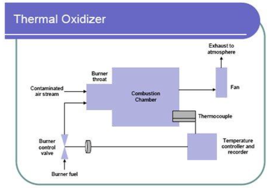
THERMAL OXIDIZERS
Thermal oxidizers, or thermal incinerators, are combustion devices that control VOC, CO, and volatile HAP emissions by combusting them to carbon dioxide (CO2) and water. Thermal oxidizers are like catalytic oxidizers (catalytic oxidizers use a catalyst to promote the oxidation reaction). Important design factors include temperature (a temperature high enough to ignite the organic constituents in the waste stream), residence time (sufficient time for the combustion reaction to occur), and turbulence or mixing of the combustion air with the waste gas.
To reduce fuel usage required for oxidation, thermal oxidizers frequently have some form of heat recovery. The percentage of heat recovery in the design of thermal oxidizers generally increases with decreasing inlet VOC/HAP concentration. Heat recovery may either be recuperative or regenerative. In recuperative heat recovery, heat is recovered by passing the hot exhaust gases through a non-contact air-to-air heat exchanger, to heat the incoming air to the oxidizer. In regenerative heat recovery, hot exhaust gases and cool inlet gases are alternatively passed through a fixed bed, typically employing ceramics. See the link below for a schematic of a basic thermal oxidizer.
WELLHEAD CONTROL PANELS AND HYDRAULIC POWER UNITS
The purpose of a WHCP is to monitor the Subsurface Controlled Safety Valves (SCSSV), Surface Safety Valves (SSV), and other wellhead safety valves (Choke, ESD, HIPPS) for the safety of the well. A WHCP should prevent the risk of injury or damage to personnel, the environment, or equipment. Wellhead control systems are designed to be “fail-safe.” The wellhead will be programmed and controlled by PLC or SCADA systems.
The WHCP receives input signals from various gauges, including pressure, temperature, and flow gauges in the wellhead. In addition, the main inputs are from emergency shutdown systems (ESD), emergency pushbuttons, and fusible plugs. The output is generated by reading these signals, which is usually a command to shut down the valves on the wellhead to ensure the plant’s safety.
The WHCP employs both hydraulic and pneumatic components. SCSSVs are mostly installed on land wells that are operated by hydraulic power. In that case, the WHCP must include a hydraulic reservoir and pump system to maintain pressure on the subsurface valves during normal operation. On the other hand, WHCP uses pneumatics for sensing and controlling surface safety valves (SSV).
The wellhead is also known as the Christmas tree (because of its structure). The Christmas tree consists of the Subsurface Controlled Safety Valves (SCSSV), Surface Safety Valves (SSV), and other wellhead safety valves (Choke, ESD, HIPPS). These valves are used to close the well when needed. At the top of the tree structure, a pressure gauge will indicate the pressure in the tubing.
Function of a WHCP
- Shut down the well in the event of hazardous situations
- Controls the critical security parameters
- Sequential start-up and down procedure of the wellhead
- Closely monitor and control SCSSV.
- WHCP employs separate hydraulic power units (HPUs) that facilitate hydraulic pumps, accumulators, reservoirs, etc.
- Special pushbuttons are used in the panel to stop the wing valve, master valve, and SCSSV.
Types of WHCP
Single wellhead control panel
A single wellhead control panel can control only one wellhead. It manages all wellhead equipment and allows for both automated and manual shutdowns. This WHCP is utilized for monotonous or remote wells that are far from other wells. The single wellhead control panel is further divided into the following categories:
- Manual control system
- Electrical control system
- Pneumatic control system
- Solar-powered control system
- Manual control system
Employs manual hydraulic pump to supply pressure to SSV. Its main function is remote ESD, Fusible plugs, low pressure / high-pressure detection, and manual shutdown at the panel.
Electrical control system
An electrical motor controls hydraulic flow to SSV. Electrical control systems have been developed and are reliable in harsh climates or when dealing with hazardous substances in the flowline. Electric shutdown systems are more flexible, easier to deploy, and less expensive than pneumatic shutdown systems, where signalling the shutdown sensor is essential. Electric systems are considerably easier to connect with a Supervisory Control and Data Acquisition (SCADA) system for remote monitoring and control.
Pneumatic control system
It does all the main functions that other systems do. But the controlling of the hydraulic pump is through pneumatic energy. This type uses for high-power operations.
Solar-powered control system
This type of control system is most suitable for wells at remote locations. It offers energy conservation, reduces operation expense, dual power supply, the standard control feature, etc.
ODORIZING SYSTEMS
Odorizing gases is a difficult task and also the requirements and applications are very stringent and strict. Mostly Odorization was done by by-pass odorization or simply adding odorants without any control. But now a days due to strict regulations, Odorization must be performed in a continuous and proportionate way.
There comes Reliance Energy proven expertise of good years of experience and the means to create a safe and regulated way of manufacturing a regulated odorizing package.
Our Package flow rates are from 0.1 litre/hour to 30 Litres/hour and a discharge pressure from 1 Bar and 300 Bar.
A standard Odorization packages consists of,
- Controller
- Analog JB
- Digital JB
- Solenoid Operated Pumps
- Pressure Transmitter
- Level Transmitter
- Pressure Control Valve
- Pressure Indicator
- Pressure Safety Valve
- Solenoid Valve
- Flow Transmitter
- Activated charcoal filter
- Safe guarding Logic
- Flush Pot
- Calibration Pot
- E & I Consumables and Accessories
- Gas Filling line piping and valves
- Filling line piping and valves
- Tank vent piping and valves
- Out odorizing systems are suitable for all odorants. For many years now, our systems have been metering EM, DMS, TBM, THT, and sulfur-free substances for numerous customers with reliability and the utmost precision.
- The process of odorizing gases is dependent on exact metering accuracy. Our systems achieve a precision level of ±1%.
- Is able to measure even the lowest volume flows with absolute precision.
- The vessels are fitted with a visual fill level control which can be used while the pumps are being calibrated.
- The metal pump are completely diffusion-proof and fail-safe.
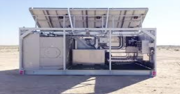
CHEMICAL INJECTION – SOLAR POWERED
Package overview
Solar Chemical Injection System was designed to provide a quality, low-maintenance, and environmentally friendly chemical injection solution.
The Solar Injection System’s lightweight, portable, and sturdy design lends itself to easy mobility in the field. Each system is prewired with industry-standard MC4 quick connectors for both the panel and the pump, ensuring minimal installation and setup time.
The entire set up was designed keeping one person in as little to assemble the package. The front access enclosure containing its battery and charge controller is raised to an easy-access level that provides clearance for rain or snow.
PUMP INSTALLATION
Design
Please check the pumps for any damage during transportation and report to Metalfab if any.
Please find the below typical P & ID for the package.
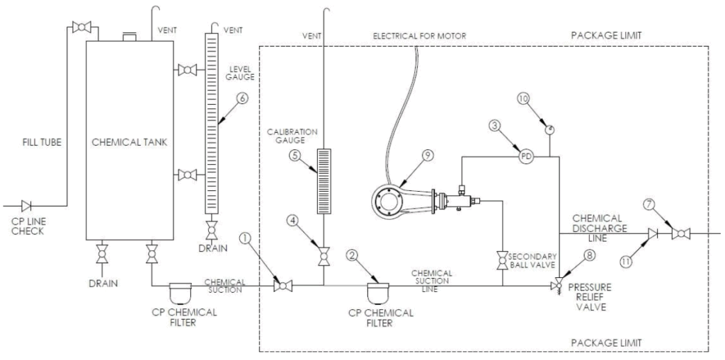
The main components of the packages are,
- Suction Line Block Valve
- Chemical Filter
- Pulsation Dampener
- Calibration Pot with Block Valve
- Tank Level Gauge
- Discharge Line Block Valve
- Pressure Relief Valve
- Injection Pumps
- Discharge Pressure Gauge
- Discharge Check valve
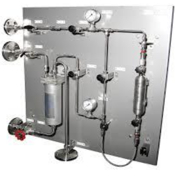
SAMPLING SYSTEM
A system that is employed in many industries that draws a sample from a process line and prepares it for analysis in an analyser.
TYPES
- Liquid Sampling
- Gas Sampling
- Liquified Gas Sampling
- Steam Water Sampling
- Mobile Sampling
LIQUID SAMPLING
- On-Off
- By-Pass
- Back Purge
- Needle Purge
- Flow Thru
- Piston Valve
- Fixed Volume
gas samplers
Gas sampler with externally coupled valves to take representative samples of gases in sample cylinders. These samplers are built from high quality stainless steel. Installation by means of threaded connections, compression fittings or flanges.
Easy to use samplers with one handle operation providing optimum safety for the operator and the environment. These samplers are standard equipped with a manual handle and mounted on a stainless-steel support plate. Spring return handles and purge options are available.
- System Purge Configuration
- By pass Purge Cylinder Configuration
- Process to Flare Configuration
LIQUIFIED gas samplers
Liquefied gas (LPG) sampler with externally coupled valves to take representative samples of liquefied gases or liquids. These samplers are built from high quality stainless steel. Installation by means of threaded connections, compression fittings or flanges. Optionally the sample cylinders can be equipped with an internal outage.
Easy to use samplers with one handle operation providing optimum safety for the operator and the environment. These samplers are standard equipped with a manual handle and mounted on a stainless-steel support plate. Spring return handles and purge options are available.
STEAM WATER SAMPLING
Sample Conditioning Panels are designed for proper conditioning of your steam and water samples. We take care from sample tap to sampling conditioning and analysis.
Standard sample conditioning panels for steam and water sampling purposes, the objective of water and steam sample conditioning is to modify and control sample temperature, pressure, and flow rate from the sample source to delivery for grab sampling or on-line analysis.
MOBILE SAMPLING SOLUTION
If there is no possibility to place fixed mounted sampling points, the mobile (transportable) sampling solution is the better choice. This is a custom made and money safe solution, we design for every application a portable sampling system for gas or liquid sampling. Mobile (transportable) sampling solutions carry with easy a several sample cylinders to the different sample tap points in your plant area.
VSD for ESP
Our VSD Assembly (Variable Speed Drive) delivers precise control over pump speed, optimizing production, reducing energy consumption, and protecting downhole equipment from electrical and mechanical stress. Engineered for reliability and seamless integration, it’s the smart choice for efficient artificial lift operations.
PCP Operation
Reliance BOPs for Progressive Cavity Pumps deliver reliable well control by preventing blowouts and safeguarding personnel, equipment, and the environment. Engineered for quick activation and dependable sealing, our BOPs ensure uninterrupted production with maximum safety compliance in oilfield operations.